- 您现在的位置:买卖IC网 > Sheet目录335 > ISL97671AIRZ (Intersil)IC LED DVR PWM CTRL 6CH 20QFN
�� �
�
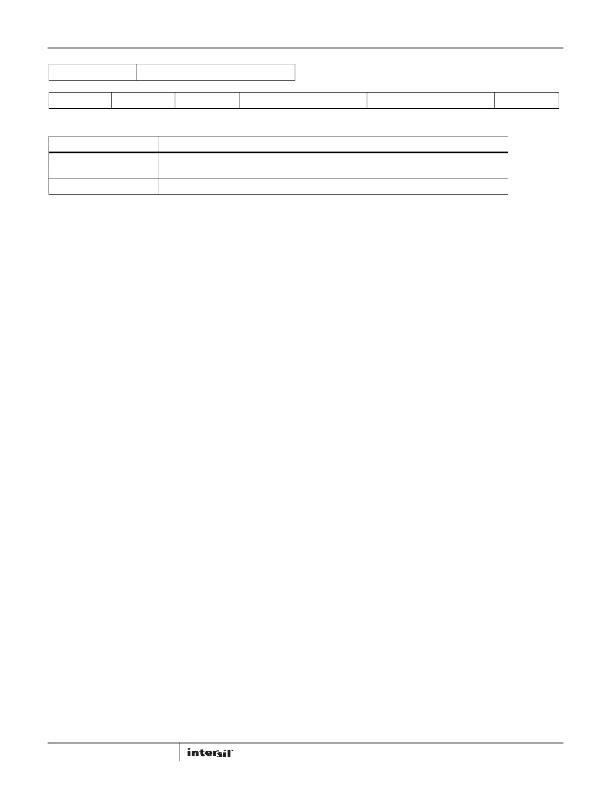
�ISL97671A�
�REGISTER� 0x0A�
�PHASE� SHIFT� CONTROL� REGISTER�
�EQUALPHASE�
�Bit� 7� (R/W)�
�PHASESHIFT6�
�Bit� 6� (R/W)�
�PHASESHIFT5�
�Bit� 5� (R/W)�
�PHASESHIFT4�
�Bit� 4� (R/W)�
�PHASESHIFT3�
�Bit� 3� (R/W)�
�PHASESHIFT2�
�Bit� 2� (R/W)�
�PHASESHIFT1�
�Bit� 1� (R/W)�
�PHASESHIFT0�
�Bit� 0� (R/W)�
�BIT� ASSIGNMENT�
�EqualPhase�
�PhaseShift[6..0]�
�BIT� FIELD� DEFINITIONS�
�Controls� phase� shift� mode� -� When� 0,� phase� shift� is� defined� by� PhaseShift<6:0>.� When� 1,� phase� shift�
�is� 360/N� (where� N� is� the� number� of� channels� enabled).�
�7-bit� Phase� shift� setting� -� phase� shift� between� each� channel� is� PhaseShift<6:0>/(255*PWMFreq)�
�FIGURE� 36.� DESCRIPTIONS� OF� PHASE� SHIFT� CONTROL� REGISTER�
�Phase� Shift� Control� Register� (0x0A)�
�The� Phase� Shift� Control� register� is� used� to� set� phase� delay�
�between� channels.� When� bit� 7� is� set� high,� the� phase� delay� is� set�
�by� the� number� of� channels� enabled� and� the� PWM� frequency.�
�Referring� to� Figure� 3,� the� delay� time� is� defined� by� Equation� 16:�
�Input� Capacitor�
�Switching� regulators� require� input� capacitors� to� deliver� peak�
�charging� current� and� to� reduce� the� impedance� of� the� input�
�supply.� The� capacitors� reduce� interaction� between� the� regulator�
�and� input� supply,� thus� improving� system� stability.� The� high�
�t� D1� =� (� t� FPWM� ?� N� )�
�(EQ.� 16)�
�switching� frequency� of� the� loop� causes� almost� all� ripple� current�
�to� flow� into� the� input� capacitor,� which� must� be� rated� accordingly.�
�where� N� is� the� number� of� channels� enabled,� and� t� FPWM� is� the�
�period� of� the� PWM� cycle.� When� bit� 7� is� set� low,� the� phase� delay� is�
�set� by� bits� 6� to� 0� and� the� PWM� frequency.� Referencing� Figure� 23,�
�the� programmable� delay� time� is� defined� by� Equation� 17:�
�A� capacitor� with� low� internal� series� resistance� should� be� chosen�
�to� minimize� heating� effects� and� to� improve� system� efficiency.�
�The� X5R� and� X7R� ceramic� capacitors� offer� small� size� and� a� lower�
�value� for� temperature� and� voltage� coefficient� compared� to� other�
�t� PD� =� (� PS� <� 6� ,� 0� >� xt� FPWM� ?� (� 255� )� )�
�(EQ.� 17)�
�ceramic� capacitors.�
�Δ� I� L� =� -------� x� Δ� t�
�V� L�
�where� PS� is� an� integer� from� 0� to� 127,� and� t� FPWM� is� the� period� of�
�the� PWM� cycle.� By� default,� all� the� register� bits� are� set� low,� which�
�sets� zero� delay� between� each� channel.� Note� that� the� user� should�
�not� program� the� register� to� have� more� than� one� period� of� the�
�PWM� cycle� delay� between� the� first� and� last� enabled� channels.�
�Components� Selections�
�According� to� the� inductor� Voltage-Second� Balance� principle,� the�
�change� of� inductor� current� during� the� switching� regulator� On�
�time� is� equal� to� the� change� of� inductor� current� during� the�
�switching� regulator� Off� time.� As� shown� in� Equations� 18� and� 19,�
�since� the� voltage� across� an� inductor� is:�
�(EQ.� 18)�
�L�
�An� input� capacitor� of� 10μF� is� recommended.� Ensure� that� the�
�voltage� rating� of� the� input� capacitor� is� able� to� handle� the� full�
�supply� range.�
�Inductor�
�Inductor� selection� should� be� based� on� its� maximum� current� (I� SAT� )�
�characteristics,� power� dissipation� (DCR),� EMI� susceptibility�
�(shielded� vs� unshielded),� and� size.� Inductor� type� and� value�
�influence� many� key� parameters,� including� ripple� current,� current�
�limit,� efficiency,� transient� performance,� and� stability.�
�Inductor� maximum� current� capability� must� be� adequate� to�
�handle� the� peak� current� in� the� worst-case� condition.� If� an�
�inductor� core� with� too� low� a� current� rating� is� chosen,� saturation�
�in� the� core� will� cause� the� effective� inductor� value� to� fall,� leading�
�to� an� increase� in� peak-to-average� current� level,� poor� efficiency,�
�and� Δ� I� L� @� On� =� Δ� I� L� @� Off,� therefore:�
�(� V� I� –� 0� )� ?� L� ×� D� ×� t� S� =� (� V� O� –� V� D� –� V� I� )� ?� L� ×� (� 1� –� D� )� ×� t� S�
�(EQ.� 19)�
�and� overheating� in� the� core.� The� series� resistance,� DCR,� within�
�the� inductor� causes� conduction� loss� and� heat� dissipation.� A�
�shielded� inductor� is� usually� more� suitable� for� EMI-susceptible�
�where� D� is� the� switching� duty� cycle� defined� by� the� turn-on� time�
�over� the� switching� period.� V� D� is� a� Schottky� diode� forward� voltage�
�that� can� be� neglected� for� approximation.�
�Rearranging� the� terms� without� accounting� for� V� D� gives� the� boost�
�ratio� and� duty� cycle,� respectively,� as� shown� in� Equations� 20� and� 21:�
�applications� such� as� LED� backlighting.�
�The� peak� current� can� be� derived� from� the� voltage� across� the�
�inductor� during� the� Off� period,� as� shown� in� Equation� 22:�
�IL� peak� =� (� V� O� ×� I� O� )� ?� (� 85%� ×� V� I� )� +� 1� ?� 2� [� V� I� ×� (� V� O� –� V� I� )� ?� (� L� ×� V� O� ×� f� S� )� ]�
�(EQ.� 22)�
�V� O� ?� V� I� =� 1� ?� (� 1� –� D� )�
�D� =� (� V� O� –� V� I� )� ?� V� O�
�24�
�(EQ.� 20)�
�(EQ.� 21)�
�The� value� of� 85%� is� an� average� term� for� the� efficiency�
�approximation.� The� first� term� is� average� current� that� is� inversely�
�proportional� to� the� input� voltage.� The� second� term� is� inductor�
�current� change� that� is� inversely� proportional� to� L� and� f� S� .� As� a�
�result,� for� a� given� switching� frequency� and� minimum� input�
�voltage� at� which� the� system� operates,� the� inductor� I� SAT� must� be�
�chosen� carefully.�
�FN7709.3�
�November� 30,� 2012�
�发布紧急采购,3分钟左右您将得到回复。
相关PDF资料
ISL97672AIRZ
IC LED DRVR LOW DIMMING 20QFN
ISL97672BIRZ
IC LED DRVR BACKLIGHT 20QFN
ISL97675IRZ-TK
IC LED DVR PWM CTRL 4CH 20QFN
ISL97677IRZ
IC LED DVR PWM CTRL 8CH 32QFN
ISL97678IRZ
IC LED DVR PWM DIMMING 8CH 32QFN
ISL97686IRTZ
IC LED DRVR BACKLIGHT 28TQFN
ISL97691IRTZ-TK
IC LED DRVR BACKLIGHT 3D 16TQFN
ISL97693IRTZ-TK
IC LED DRVR BACKLIGHT 16TQFN
相关代理商/技术参数
ISL97671AIRZ-T
功能描述:IC LED DRVR 6-CH BACKLIGHT 20QFN RoHS:是 类别:集成电路 (IC) >> PMIC - LED 驱动器 系列:- 标准包装:60 系列:- 恒定电流:- 恒定电压:- 拓扑:线性(LDO),PWM,升压(升压) 输出数:8 内部驱动器:是 类型 - 主要:背光 类型 - 次要:RGB,白色 LED 频率:500kHz ~ 1.5MHz 电源电压:4.75 V ~ 26 V 输出电压:45V 安装类型:* 封装/外壳:* 供应商设备封装:* 包装:* 工作温度:-40°C ~ 85°C
ISL97671AIRZ-TK
功能描述:IC LED DVR PWM CTRL 6CH 20QFN RoHS:是 类别:集成电路 (IC) >> PMIC - LED 驱动器 系列:- 标准包装:60 系列:- 恒定电流:- 恒定电压:- 拓扑:线性(LDO),PWM,升压(升压) 输出数:8 内部驱动器:是 类型 - 主要:背光 类型 - 次要:RGB,白色 LED 频率:500kHz ~ 1.5MHz 电源电压:4.75 V ~ 26 V 输出电压:45V 安装类型:* 封装/外壳:* 供应商设备封装:* 包装:* 工作温度:-40°C ~ 85°C
ISL97671IRZ
制造商:Intersil Corporation 功能描述:6-CH LED DRIVER WITH I2C CONTROL - Rail/Tube
ISL97671IRZ-EVALZ
功能描述:BOARD EVALUATION FOR ISL97671 RoHS:是 类别:编程器,开发系统 >> 评估板 - LED 驱动器 系列:- 标准包装:1 系列:PowerWise® 电流 - 输出 / 通道:20mA 输出及类型:1,非隔离 输出电压:17V 特点:可调光 输入电压:2.7 ~ 5.5 V 已供物品:板 已用 IC / 零件:LM3508 相关产品:LM3508TLX-ND - IC LED DRVR WHT BCKLGT 9USMDLM3508TLDKR-ND - IC LED DRVR WHT BCKLGT 9MICROSMDLM3508TLCT-ND - IC LED DRVR WHT BCKLGT 9MICROSMDLM3508TLTR-ND - IC LED DRVR WHT BCKLGT 9MICROSMD
ISL97671IRZ-T
制造商:Intersil Corporation 功能描述:6-CH LED DRIVER WITH I2C CONTROL - Tape and Reel
ISL97671IRZ-TK
制造商:Intersil Corporation 功能描述:6-CH LED DRIVER WITH I2C CONTROL, 1K T&R - Tape and Reel
ISL97672AIRZ
功能描述:IC LED DRVR LOW DIMMING 20QFN RoHS:是 类别:集成电路 (IC) >> PMIC - LED 驱动器 系列:- 产品培训模块:Lead (SnPb) Finish for COTS
Obsolescence Mitigation Program 标准包装:2,500 系列:- 恒定电流:- 恒定电压:- 拓扑:升压(升压),切换式电容器(充电泵) 输出数:1 内部驱动器:是 类型 - 主要:背光 类型 - 次要:白色 LED 频率:625kHz ~ 875kHz 电源电压:2.7 V ~ 5.3 V 输出电压:5V 安装类型:表面贴装 封装/外壳:10-TFSOP,10-MSOP(0.118",3.00mm 宽) 供应商设备封装:10-µMAX 包装:带卷 (TR) 工作温度:-40°C ~ 85°C
ISL97672AIRZ-T
功能描述:IC LED DRVR LOW DIMMING 20QFN RoHS:是 类别:集成电路 (IC) >> PMIC - LED 驱动器 系列:- 产品培训模块:Lead (SnPb) Finish for COTS
Obsolescence Mitigation Program 标准包装:2,500 系列:- 恒定电流:- 恒定电压:- 拓扑:升压(升压),切换式电容器(充电泵) 输出数:1 内部驱动器:是 类型 - 主要:背光 类型 - 次要:白色 LED 频率:625kHz ~ 875kHz 电源电压:2.7 V ~ 5.3 V 输出电压:5V 安装类型:表面贴装 封装/外壳:10-TFSOP,10-MSOP(0.118",3.00mm 宽) 供应商设备封装:10-µMAX 包装:带卷 (TR) 工作温度:-40°C ~ 85°C